Contrary to common belief, the NEC generally doesn't require you to size conductors to accommodate voltage drop. It merely suggests in the Fine Print Notes to 210.19(A), 215.2(A)(4), 230.31(C), and 310.15(A)(1) that you adjust for voltage drop when sizing conductors. It's important for you to remember that Fine Print Notes are recommendations, not requirements [90.5(C)].
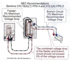
The NEC recommends that the maximum combined voltage drop for both the feeder and branch circuit shouldn't exceed 5%, and the maximum on the feeder or branch circuit shouldn't exceed 3% (Fig. 1). This recommendation is a performance issue, not a safety issue.
If the NEC doesn't require you to size for voltage drop, why even think about it? Consider these reasons:
The voltage drop of a circuit is in direct proportion to the resistance of the conductor and the magnitude of the current. If you increase the length of a conductor, you increase its resistance — and thus increase its voltage drop. If you increase the current, you increase the conductor voltage drop. Thus, long runs often produce voltage drops that exceed NEC recommendations.
To test your knowledge, take the following pop quiz. What is the minimum NEC-recommended operating voltage for a 115V load connected to a 120V source (Fig. 2)?
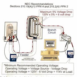
The maximum conductor voltage drop recommended for both the feeder and branch circuit is 5% of the voltage source (120V). The total conductor voltage drop (feeder and branch circuit) shouldn't exceed 120V×0.05=6V. Calculate the operating voltage at the load by subtracting the conductor voltage drop from the voltage source: 120V - 6V = 114V. Therefore, the correct answer is (c), 114V.
You can determine conductor voltage drop by using the Ohm's Law method or by the formula method, but you can only use the Ohm's Law method (I × R) for single-phase systems. Regardless of which method you use, observe the following:
Let's do a sample calculation using the Ohm's Law method. What is the voltage drop of two 12 AWG THHN conductors that supply a 16A, 120V load located 100 feet from the power supply?
(a) 3.2V
(b) 6.4V
(c) 9.6V
(d) 12.8V
The math is straightforward:
I = 16A
R = 2 ohms per 1,000 feet, according to Chapter 9, Table 9: (2 ohms ÷ 1,000 ft) × 200 ft = 0.4 ohms
VD = I × R
VD = 16A × 0.4 ohms = 6.4V
Therefore, the correct answer is (b), 6.4V.
This method is slightly more involved than the Ohm's Law method, but the big advantage is you can use it for single-phase or 3-phase systems. Here are some additional items to observe:
Let's look at a 3-phase example. A 3-phase, 36kVA load rated 208V is wired to the panelboard with 80-foot lengths of 1 AWG THHN aluminum. What is the approximate voltage drop of the feeder circuit conductors?
(a) 3.5V
(b) 7V
(c) 3%
(d) 5%
Applying the 3-phase formula, where:
K = 21.2 ohms, aluminum
I= [36,000VA ÷ (208V × 1.732)] = 100A
D = 80 ft
CM = 83,690 (obtained from Chapter 9, Table 8)
VD = (1.732 × 21.2 × 100A × 80 ft) ÷ 83,690 CM = 3.51V
Therefore, the correct answer is (a), 3.5V.
Don't forget to verify that you haven't exceeded the recommended Code requirement of a 3% voltage drop at the end of the branch circuit or feeder.
%VD = (3.51V ÷ 208V) × 100 = 1.69%
Using basic algebra, you can apply the same basic formula to find one of the other variables if you already know the voltage drop. For example, suppose you want to know what size conductor you need to reduce the voltage drop to the desired level. Simply rearrange the formula. For 3-phase, it would look like this:
CM (3-phase) = (1.732 × K × I × D) ÷ VD
Remember, for single-phase calculations you would use 2 instead of 1.732.
Suppose you have a 3-phase, 15kVA load rated 480V and 390 feet of conductor. What size conductor will prevent the voltage drop from exceeding 3% (Fig. 3)?
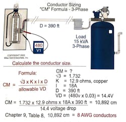
CM = (1.732 × 12.9 × 18A × 390 ft) ÷ 14.4V = 10,892 CM (8 AWG, Chapter 9, Table 8)
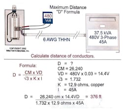
You could also rearrange the formula to solve a problem like this one: What is the maximum length of 6 AWG THHN you can use to wire a 480V, 3-phase, 37.5kVA transformer to a panelboard so voltage drop doesn't exceed 3% (Fig. 4 )?
 is simple if you know the circular mils and direct-current constant of the circuit conductor, load in amperes at 100%, and assume a minimum voltage drop of 3%." width="250" height="" />
CM = 26,240 (6 AWG Chapter 9, Table 8)
VD = 480V × 0.03 = 14.4V
K = 12.9 ohms, copper
I = [37,500VA ÷ (480V × 1.732)] = 45A
D = (26,240 CM × 14.4V) ÷ (1.732 × 12.9 ohms × 45A) = 376 ft
Sometimes, the only way to limit voltage drop is to limit the load. Again, you can rearrange the basic formula algebraically: I = (CM × VD) ÷ (1.732 × K × D). Suppose an installation contains 1 AWG THHN conductors, 300 feet long in an aluminum raceway fed by a 3-phase, 460/230V power source. What is the maximum load the conductors can carry without exceeding the NEC recommendation for voltage drop (Fig. 5)? Let's walk through the required calculation:
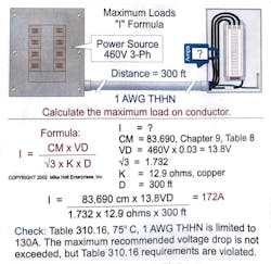
I = (CM × VD) ÷ (1.732 × K × D)
CM = 83,690 (1 AWG, Chapter 9, Table 8)
VD = 460V × 0.03 = 13.8V
K = 12.9 ohms, copper
D = 300 ft
I = (83,690 CM × 13.8V) ÷ (1.732 × 12.9 ohms × 300 ft) = 172A
Note: The maximum load permitted on 1 AWG THHN at 75°C is 130A [110.14(C) and Table 310.16].
The NEC doesn't require you to do voltage drop calculations because they aren't involved in issues of safety, but that doesn't mean they aren't important. A system that meets NEC requirements may not be efficient in terms of power consumption or optimum in terms of equipment longevity and performance. As the old saying goes, “Wire is cheap, but performance loss is costly.” First, ensure that your system meets NEC requirements. Then look at it for voltage drop so you get the right cost tradeoffs between performance and cost.